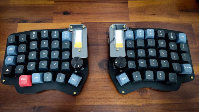
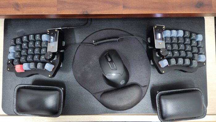
As presented in my previous post, I use a split ortholinear keyboard as my daily-driver. This keyboard use a layout called Sofle v1, designed by Josef Adamcik. Out of the box, it was a wired keyboard: the two halves are connected with a TRRS cable, and the computer is connected to the left half.
The great thing about wired peripherals is that they “just work”. No need to set up connection nor pairing, and no battery to worry about. Plug-and-play, simple as that.
That was my thought for the first 5 months owning this keyboard. Wires never bothered me that much. However, further down the line, 2 problems started to become more prominent for me:
- The two halves of the keyboard are connected using TRS connectors.
- The default MCU boards is too limiting.
The problem with TRS
TRRS connectors, or more commonly known as 3.5mm jack, are used to help the right side of the keyboard to receive power and send back signals to the left side. However, by design, this connector does NOT support hot plug. This means that, you are not supposed to plug and unplug the plug while the socket is being powered.
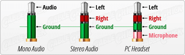
“Left” and “Right” rings are the ones that transmit power and signal. While unplugging, “Left” ring will get in contact with the pad that supposed to connect with “Right” ring, and “Right” ring will get in contact with the pad that supposed to connect with “Ground” ring. This will cause a brief electrical short, which the MCU can cope with if it is fast and brief. However, it can potentially caused permanent damage to the board if the electrical short is prolonged. This problem was also mentioned by the designer of the board (see this link, “Warnings and disclaimers” section).
TRS connectors is not very secured. It does not have locking mechanism, and is designed to be plug and unplug regularly. This is not what I want to have for a keyboard connector.
The problem with default MCU
Like most modern open-source keyboard layout, Sofle v1 use an MCU (micro-controller unit) as its “brain”. Instead of a hard-coded controller chip, these board benefits from programmable controllers that will help their users to customized how their keyboard will behaved. There are many options out there, and the one that Sofle v1 used is based on the footprint of Arduino Pro Micro, and the boards that came with it by default use an ATmega32u4 MCU. Long story short, this MCU is both very slow and has very little memory compared to other popular options:
| Board | MCU | Architecture | Clock | Flash | RAM |
|---|---|---|---|---|---|
| nRFMicro | nRF52840 | 32-bit Cortex M4 | 64 Mhz | 1 MB | 256 kB |
| Pro Micro | ATmega32u4 | 8-bit AVR | 16 Mhz | 32 kB | 2.5 kB |
| Bluepill | STM32F103C8T6 | 32-bit Cortex M4 | 72 Mhz | 64 kB | 20 kB |
| Proton-C | STM32F303CCT6 | 32-bit Cortex M4 | 72 Mhz | 256 kB | 40 kB |
This caused a major limitation as to how complicated and feature-packed the customized firmware can be, which in turn greatly curb the potential of an open platform. And this, unlike my previous point about TRS connector, is not what I feared will happened. I stumbled on this limitation when I was trying to add more advanced features provided by QMK to the board, but the compiler cannot complete the task successfully since it detected that the compiled firmware size exceeded 32 kB. The default firmware is already filled up around 80% of the total 32 kB so there was not much room to play with. Even the RAM is limited in size on this chip, making it very limiting on how many pre-defined macros, combos, tap dance and other additional behaviors you can stored in the memory.
For most people, this might not be a major problem. But for me, I want my keyboard to be truly “the only limit is your imagination”. That’s why, during my semester break, I started to look into alternative options. This is when I found out about the nRF52840 MCU, which conveniently solved both of my problems at the same time!
Solution
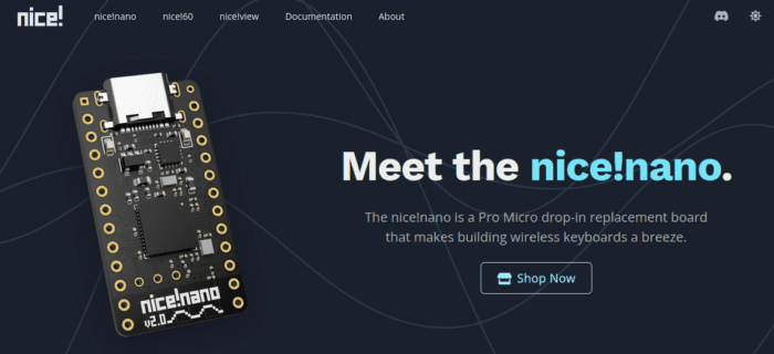
Since Sofle v1 was designed to work with a Pro Micro board, the most important requirement for the alternative is that it is compatible with that pin out configuration. One of the most popular option is the nice!nano board. This board has built-in Bluetooth controller, compatible with Pro Micro pin out configuration, and has two additional pins near the USB port to connect to a battery for power.
However, they don’t have an official reseller here in my country, and the shipping fee is even higher than the board themselves! Thus I had to resorted to getting clone boards from Shopee (one of the largest e-commerce platform in Vietnam). The clone version has a different component layout but use the same MCU and has comparatively similar specifications. The price is significantly lower ($5 vs. $25), but since the clones are shipped directly from China, I can see the reason for the difference.
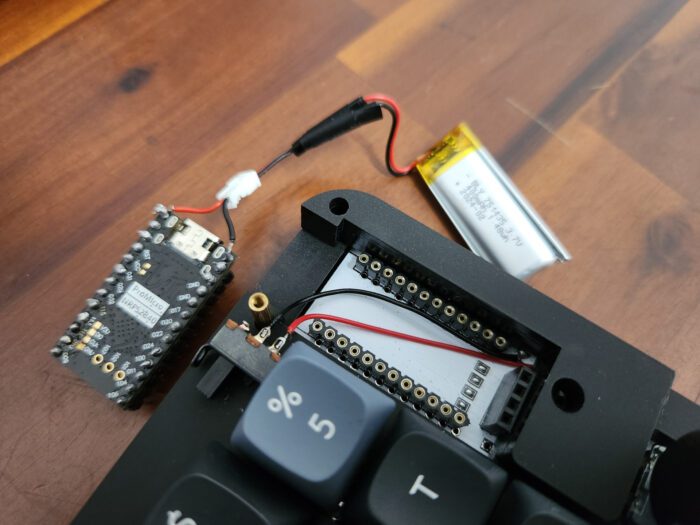
After received the boards, I solder the rails onto them. My keyboard use machine rails which is incompatible with the one that came with the boards, I had to buy them separately. I left out the top 2 pins to connect to a JST 1.25mm connector, which then connect to a 3.7v LiPo battery. The one I used is the 751435 – 400mAh variation. According to ZMK’s Power Profiler, this should last me around 2 months of normal usage without RGB LEDs and screen. Due to the size of the battery, I cannot tuck it under the board, so I took out the OLED screen and placed the battery on top instead. Not using the OLED screen will significantly prolonged the battery life so I didn’t plan to use it anyway.
To get start with using the board, I simply followed the very straightforward and detailed guide provided in ZMK’s documentation. To make the configuration process simpler, I used Nick Coutsos’ Keymap Editor. This amazing web app made things so much easier for me to customize my firmware!
The switch on top of the number 5 keycap in the image is connected to the “Reset” pads of the board. I placed it their because the case doesn’t have a hole for a switch to be mount directly on top of the pads. This board was designed for wired usage, so no power switch pads are present on the PCB. The keyboard can be put into “Off” state by using ZMK’s Soft Off. The simplest way to wake the keyboard up from this state is to toggle the “Reset” button.
Everything a long the steps I took until the final result did not encounter any roadblock. This is thanks to the amazing job of the ZMK community! Although the project is relatively new to the scene, with many features to become stable, its current state and future is very promising.
Once again, big shout out to Josef Adamcik, Nick Coutsos and the ZMK community for paving the path for me to accomplish this amazing build!